
Nokia 3310 Hardware Teardown
For the Nokia 3310 Game Jam, I built Trick Shot II a small physics game which runs both on desktop and a custom PCB I built to fit inside a classic Nokia 3310 phone.
Useful links:
- 3310_engine a game engine I developed to run games on desktop and hardware for a Nokia 3310
- 3310_pico a custom PCB I designed to replace the proprietary PCB in a Nokia 3310/3315
Most of the Nokia 3310 hardware is proprietary. I found some schematics online (see 3310-schematics), but they include a bunch of custom chips which have no documentation.
Rather than work with an SDK and programming interface which I had no experience with, I decided to break the hardware interfaces down, and replace the PCB inside a 3310 with my own custom PCB. One thing I found interesting is that the 3310/3315 models have identical hardware, so swapping the internal PCBs for either will work.
The Nokia 3310’s PCB is 1mm thick - unfortunately, I made a mistake when ordering my first run and got a 1.6mm board. It works, but the full assembly doesn’t clip together nicely.
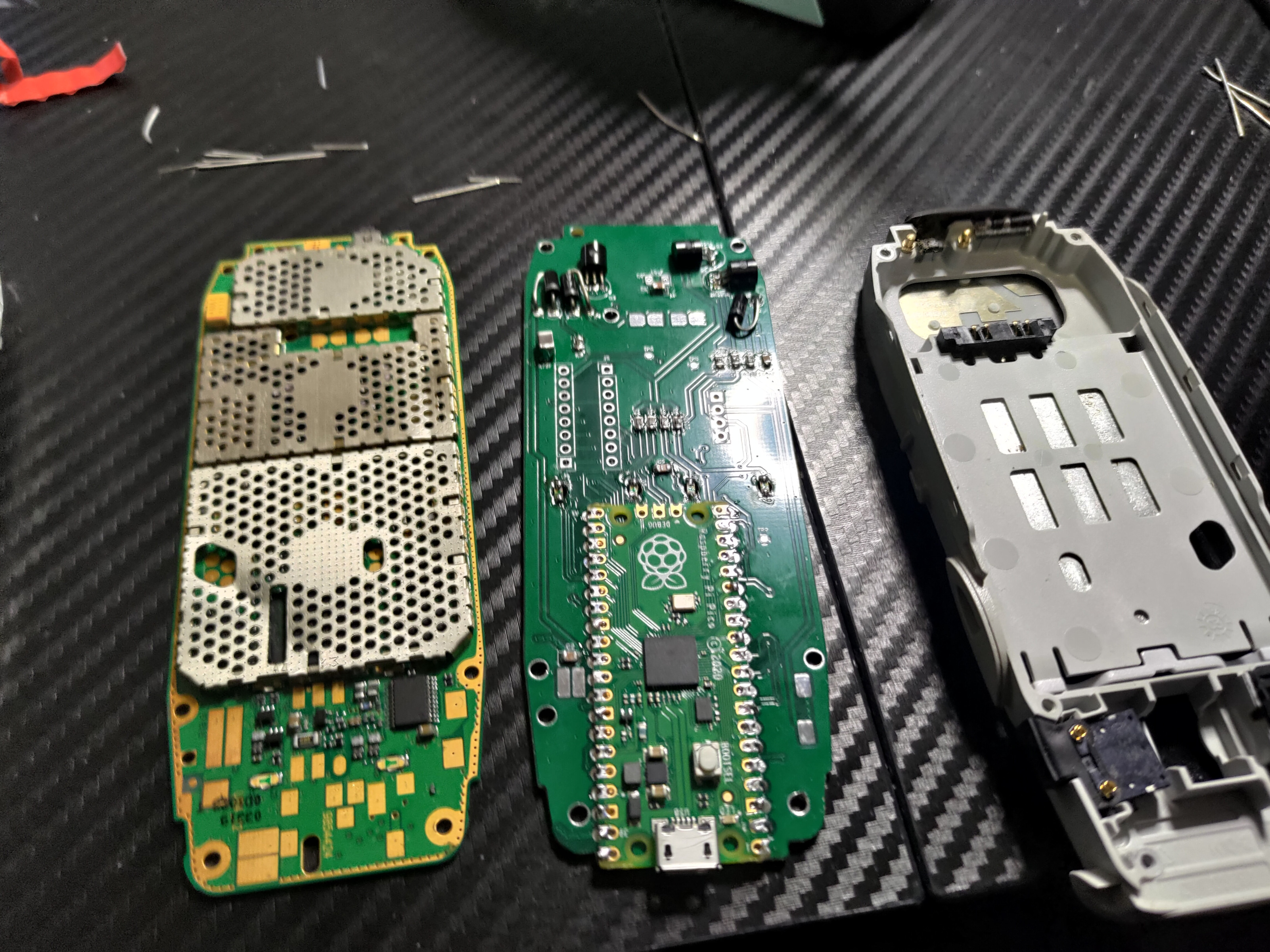
This is the Nokia 3310’s PCB next to the first revision of a custom board I made to drive the buzzer, screen, vibrator, leds and keypad. The interface between the PCB and other modules are all pressfit where exposed pads are pressed up against spring connectors on the battery, screen, buzzer and vibrator.
Front and Back
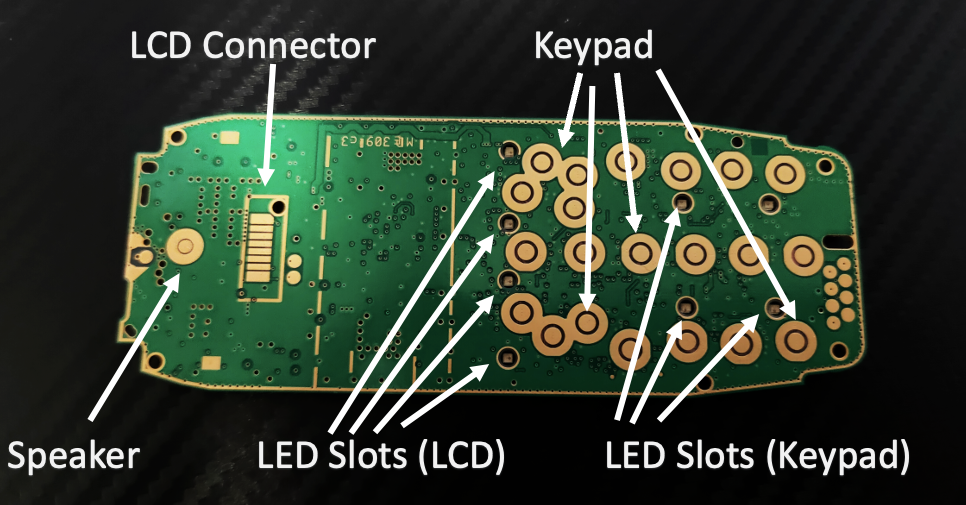
The front of the board interfaces with the keypad, screen, leds and speaker.
The keypad buttons are made up of a circular pad with an outer ring, shorting these results in a button press being detected. The actual buttons on the Nokia phone consist of a rubber button and metal diaphram which shorts these pads when pressed. The pads are arranged in a matrix of rows and columns to reduce the number of hardware IO.
The front of the board presses up against an assembly holding the screen, light tunnels, speaker and keypad. This assembly requires that the front surface of the board must be completely flat. For the LEDs to provide light, they are soldered to the back of the board, but pointing inwards through 2mm holes so they shine through to the front side.
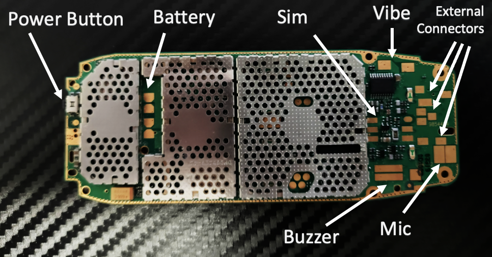
The back of the board has many interfaces, notably:
- battery pads are located just behind where the screen is
- vibration motor and buzzer are on the bottom near the sides
The main limitations when designing hardware to fit in here is:
- avoiding placing components over the pads
- the overall height of most components must be under 2mm.
- there is slightly more space near the power button because that part of the assembly has a cavity for the antenna
LCD Screen
The Nokia 3310 has a 84x48 monochrome LCD based on the PCD8544 driver.
Screen Update Rate and Response Times
The screen updates at up to 67Hz, but the response time is quite slow.
- Pixel Empty->Fill: ~50ms
- Pixel Fill->Empty ~125ms
You can see it here:
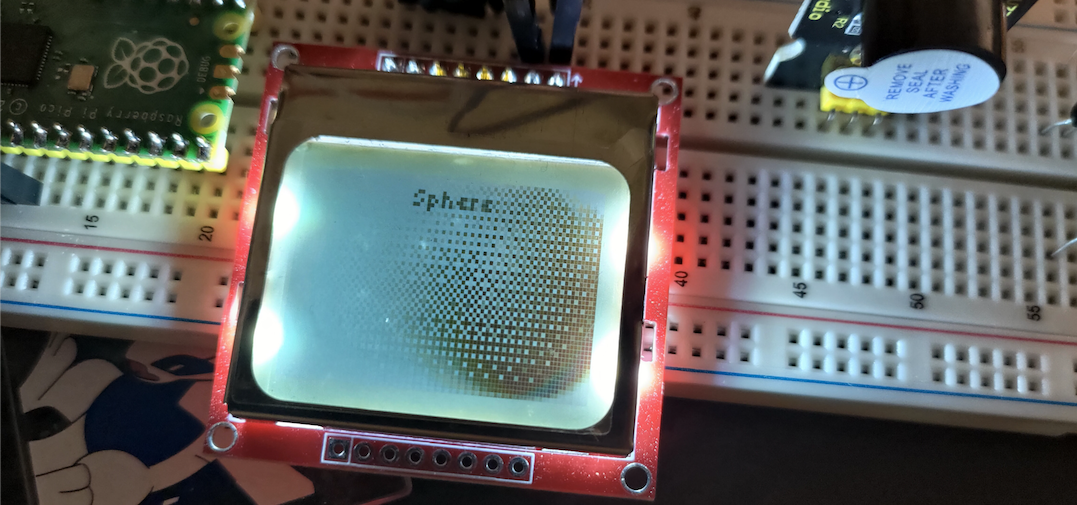
The image shows a sphere moving from left to right, the LCD respons time results in ghosting behind the sphere.
On the leading edge, there is a response time of around 50ms, you can see this near the right edge of the screen where the pixels of the sphere are still forming.
Screen Flashing
If you are like me, you may see the response time on the screen as an opportunity, like “hey if I flash pixels on and off really fast, I will get in-between shades!”
I experimented with this with the following procedure:
- Draw a square on the top left corner, always empty
- Draw a square on the top right corner, always filled
- All other pixels flash every second frame
The result is a mess:
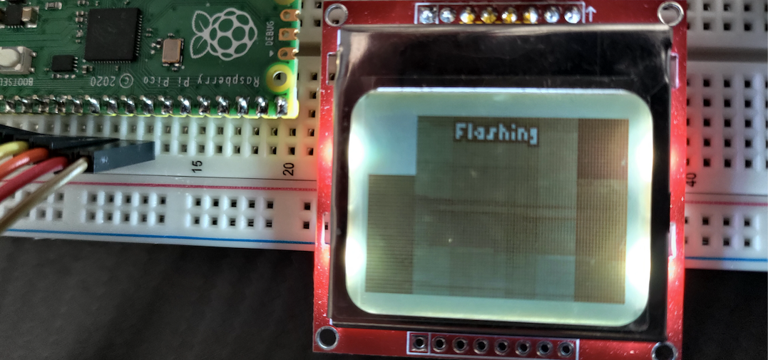
There are clear darker zones beneath the two rectangles, but the faded effect across the LCD is uneven… so yes you can get in-between shades, but they are uneven, noisy and look terrible.
Screen Pixel Dimentions
The dimensions of the LCD module for the PCD8544 is roughly 30.5 by 21.5mm. Dividing by the number of pixels 84 by 48, we get a single pixels dimension of 0.363 by 0.448. 0.448/0.363 =1.23, so I’d give this a ratio of about 4 by 5 (5/4=1.25) if emulating the pixel’s dimension - those rectangles in the “flashing” image above are actually squares, so you can see how impactful this pixel ratio is.
When making trick shot - I wanted a square grid, so I designed the game to use a 5x4 grid - these look square-enough on a real screen. I even adapted the physics engine treat 5 pixels as a single unit in width, but 4 pixels as a single unit in height so it would feel correct.
Screen Colors
When emulating a screen, there are 3 key colors:
- the color outside the draw area
- the “paper” color on the draw area, which is slightly darker
- the “ink” (dark) color
Lines between Pixels
You may notice little light lines between the pixels in the above images.
These are super thin, but interestingly they are same color as outside the draw area.
In my engine, I wrote my shader to do some color mixing to give their “impression” rather than color the lines as the outer draw area. This is because they are so thin, you’d need a super high resolution monitor to justify making them the color they are on a real screen.
Screen Color Tinting
People remember the tints on 3310s a little differently. Some remeber a harsh green, blue, light green or white tint.
These tints actually come from the backlight LEDs that have been fit for a specific phone.
Buzzer
The buzzer is driven by a square wave. I haven’t found any solid documenation for this, but the Nokia schematics show that it’s driven by the same chip that drives the vibe motor. To be safe, I drive it as if it is an inductive load.
The frequency range of the buzzer is quite wide, although it distorts a lot at low frequencies and effectively becomes a bunch of clicks:
Vibe (Shake)
The vibration motor can be driven with a 3v3 squarewave. On Nokia’s schematics it is driven by a motor driver IC, so don’t drive this without a FET/BJT and freewheeling diode.